————————————————— DISCLAIMER ————————————————–
As been a Voltage controled AC MAINS Dimmer you can control it with:
- PWM signal
- DAC output Voltage
- or if you don’t want any kind of MCU involved, just user a 10k Potentiometer in a voltage divider as part of a simple VCNT input circuit!
In this example we will use a MCP4728 4 channels/12 Bit DAC as a VCNT (voltage control) command source for our MPDMv4 Dimmer Board.
What we will need:
- ESP8266 nEXT EVO Board
- ESP8266 nEXT EVO – Analog Extension Board – AN1
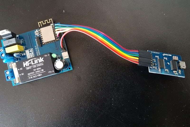
- For programming and uploading the driver and the software we will continue to use the LuaUploader as before.
Software implementation
1. MCP4728 DAC Driver
1.1 I2C Bus Initialisation
    init = function (self, sda, scl)
          self.id = 0
          i2c.setup(self.id, sda, scl, i2c.SLOW)
    end
    dac = function(self, ch_reg,voltage)
          volt=(voltage*4096)/vcal
          msb = bit.rshift(volt, 8)
          lsb = volt-bit.lshift(msb,8)
          i2c.start(id)
          i2c.address(id, dac_addr ,i2c.TRANSMITTER)
          i2c.write(id,ch_reg)
          i2c.write(id,msb)
          i2c.write(id,lsb)
          i2c.stop(id)
    end
1.3 Set DAC Register
   set_reg_dac = function(self, reg)
          i2c.start(id)
          i2c.address(id, dac_addr ,i2c.TRANSMITTER)
          i2c.write(id,ch_reg)
          i2c.stop(id)
     end
2. MAIN Program
id=0
sda=2
scl=1
dac_addr=0x60
ch_reg=0x58      -- DAC CH A - Ext REF -
vcal=3.2325      -- external voltage reference = Vcc

require('mcp4728')           --call MCP4728 Driver module
mcp4728:init(sda, scl)       --Init I2C BUS
mcp4728:dac(ch_reg,2.8)      --Set VCMD Voltage (0-2.8V)
2.1 Dimming stage example based on timer :
vcmd=0
tmr.alarm( 0, 1000, 1, function()
    print("Set VCMD value : "..vcmd)
    mcp4728:dac(ch_reg,vcmd)
    vcmd=vcmd+0.10
    if (vcmd>=2.81) then vcmd=0 end
end)
tmr.stop(0) --stop the timer when you want to finnish cycling thru dimmer stages.
MPDMv4 by ESP8266-Projects.com is licensed under a Creative Commons Attribution-NonCommercial 4.0 International License.


